And no, I didn't just pop a bow tie on my doorbell! I recently installed Home Assistant on a spare Raspberry Pi I had laying around, and though our house isn't very smart-enabled, I thought it wouldn't be too hard to improve our cheap doorbell to notify through our Google home speakers (or even phone).
TL;DR: although I went down the path of installing a module inside the doorbell receiver, this wasn't the sensible solution (due to battery drain) and I settled with a 433Mhz receiver to do the job.
There's quite a bit of detail in this post, because I think the methods are reusable beyond a doorbell, but in "upgrading" any dumb (also known as "regular") hardware.
Smart control over a doorbell
What I have:
- A doorbell run on a coin cell (literally velcro'ed to the front door)
- The doorbell receiver that has a speaker, an LED and 2 AA batteries
My plan:
- When the doorbell is being pressed, the LED on the receiver lights up
- Attach to the LED to piggyback the signal going HIGH
- Using an ESP01 (tiny and cheap) running esphome then sends data to Home Assistant
- Bonus extra: track battery level in receiver so I know when to change the batteries
- Bonus extra: ability to control the speaker (so it doesn't "ring" before 8am)
Components used:
- ESP01, a wifi enabled controller - just because I had a few and there's enough pins on it, though any ESP8266 would work
- INA219, a component to track voltage and current over I2C
The software used to manage the interfacing from the ESP's pins was ESPHome a fairly powerful and configuration driven system.
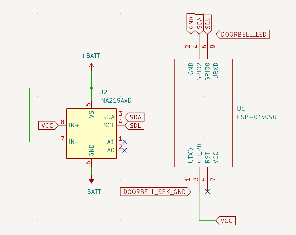
Note the best schematic, but this is the wiring I've used:
I use an ESP development board programmer to flash the ESPHome firmware.
The configuration of the firmware configuration boils down to this important snippet:
binary_sensor:
  - platform: gpio
    pin:
      number: RX
      inverted: True
      mode:
        input: True
    name: "Doorbell Button"
    filters:
      - delayed_on: 10ms
      - delayed_off: 10ms
    on_press:
      then:
        - mqtt.publish:
            topic: doorbell/button
            payload: 'pressed'
I found that the LED in the doorbell receiver was controlled by the expoxy coated IC pulling one of the pins to ground, so I needed to connect to the correct side of the resistor (being used to protect the LED) and then when it went LOW I knew the LED was being lit up and thusly the doorbell had been pressed.
See full esphome-doorbell.yaml listing
substitutions:
  wifi_ssid:
  wifi_password:
  broker_ip:
  broker_username:
  broker_password:
  name: esphome-doorbell
  friendly_name: doorbell
# remember to fill those in


esphome:
  name: ${name}
  friendly_name: ${friendly_name}
  min_version: 2024.6.0
  name_add_mac_suffix: false
  project:
    name: esphome.web
    version: '1.0'

esp8266:
  board: esp01_1m

# Enable logging
logger:

# Enable Home Assistant API
api:

# Allow Over-The-Air updates
ota:
- platform: esphome

# Allow provisioning Wi-Fi via serial
improv_serial:

wifi:
  ssid: ${wifi_ssid}
  password: ${wifi_password}

  # Enable fallback hotspot (captive portal) in case wifi connection fails
  ap:
    ssid: 'Doorbell Fallback Hotspot'
    password: 'doorbell'


# In combination with the `ap` this allows the user
# to provision wifi credentials to the device via WiFi AP.
captive_portal:

dashboard_import:
  package_import_url: github://esphome/example-configs/esphome-web/esp8266.yaml@main
  import_full_config: true

# To have a "next url" for improv serial
web_server:

mqtt:
  broker: ${broker_ip}
  username: ${broker_username}
  password: ${broker_password}
  discovery: true
  discovery_prefix: homeassistant

binary_sensor:
  - platform: gpio
    pin:
      number: RX
      inverted: True
      mode:
        input: True
    name: "Doorbell Button"
    filters:
      - delayed_on: 10ms
      - delayed_off: 10ms
    on_press:
      then:
        - mqtt.publish:
            topic: doorbell/button
            payload: 'pressed'

switch:
  - platform: gpio
    pin:
      number: TX
      mode:
        output: True
    name: "Speaker active"

i2c:
  sda: GPIO2
  scl: GPIO0
  scan: True

sensor:
  - platform: ina219
    address: 0x40
    shunt_resistance: 0.1 ohm
    current:
      name: "Current"
    power:
      name: "Power"
    bus_voltage:
      name: "Bus Voltage"
    shunt_voltage:
      name: "Shunt Voltage"
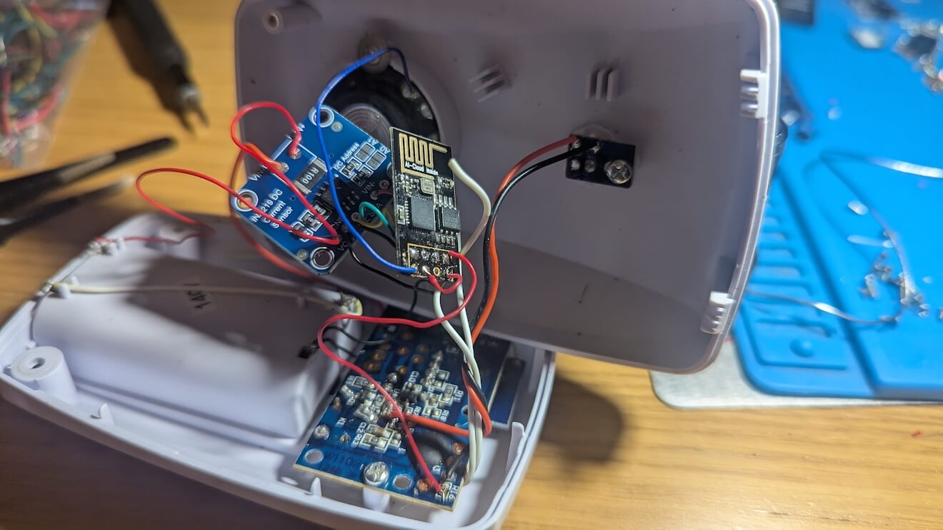
After some soldering (and accidentally wiring the INA219 incorrectly causing a short circuit 🙈) I ended up with a working "smart"(ish) doorbell:
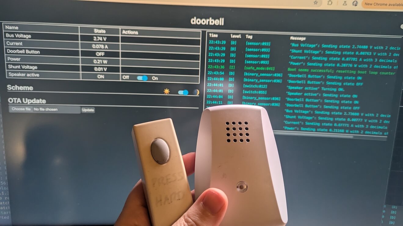
With the web UI showing off the glorious power information and states:
However…
I was already missing one extra part for my project: a voltage step-up/boost for the ESP module.
Apparently ESPs can be picking about having a stable 3v3 DC power supply - which two AA batteries can't provide, so I had intended to add in a a TMS61023 - which provides 5v but can be adjusted to 3v3 by swapping out the resistors.
This would give me the correct voltage to the ESP to run reliably. That combined with the clever INA219 component to track and notify of low battery and it would be "perfect".
Except… I needed to a do a little maths first.
The new components inside the doorbell receiver, the ESP in particular in idle state, was drawing around 70mAh. In the best scenario of having fresh batteries, that could hold (lets say on average) 2500mAh, that would mean the batteries would last… around 70 hours (2500 / 70 * 2). Less than 3 days 🤦.
Flip the script, use 433Mhz
Instead of going inside the receive (which, I still maintain is clever, but really not sensible on batteries), apparently it's not uncommon to use a RF receiver at 433Mhz to sniff for the doorbell message.
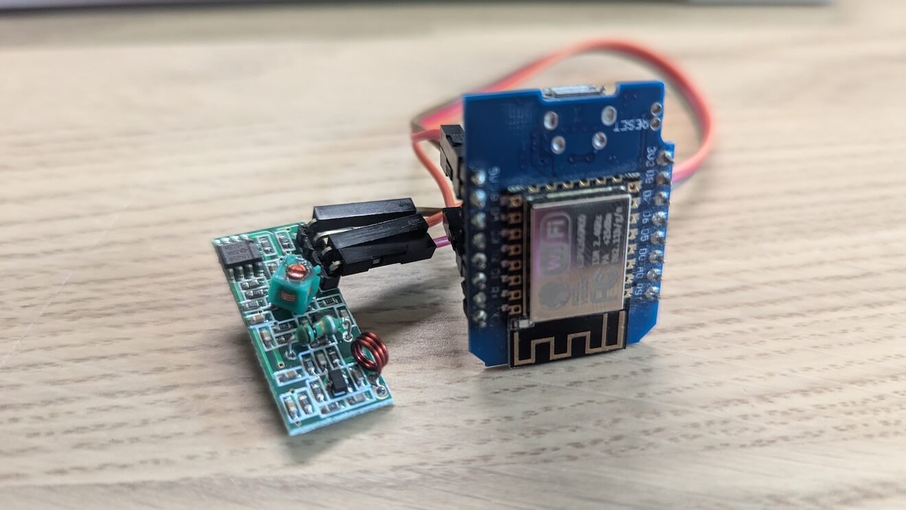
I happened to have a few laying around from an unknown project, and wiring up was a matter of VCC, GND and a data pin.
The first problem I ran into was that the RF receiver requires 5v which the ESP doesn't use, but I also have a lot of Wemos D1 Minis which do have a 5v line so I swapped out the microcontroller (which still works with ESPHome) and had this:
The first phase was to detect the doorbell signal. Using this configuration flashed to the ESP, I was able to log any RF signals, and with the doorbell button pressed down I immediately saw a report.
remote_receiver:
  pin: GPIO5
  dump:
    - rc_switch
  tolerance: 50%
  filter: 250us
  idle: 4ms
The log looked like this when I pressed the doorbell:
[23:43:05][I][remote.rc_switch:261]: Received RCSwitch Raw: protocol=6 data='111100100011'
[23:43:05][I][remote.rc_switch:261]: Received RCSwitch Raw: protocol=6 data='111100100011'
[23:43:05][I][remote.rc_switch:261]: Received RCSwitch Raw: protocol=6 data='111100100011'
[23:43:05][I][remote.rc_switch:261]: Received RCSwitch Raw: protocol=6 data='111100100011'
[23:43:05][I][remote.rc_switch:261]: Received RCSwitch Raw: protocol=6 data='111100100011'
[23:43:05][I][remote.rc_switch:261]: Received RCSwitch Raw: protocol=6 data='111100100011'
[23:43:05][I][remote.rc_switch:261]: Received RCSwitch Raw: protocol=6 data='111100100011'
[23:43:05][I][remote.rc_switch:261]: Received RCSwitch Raw: protocol=6 data='1111001000'
[23:43:05][I][remote.rc_switch:261]: Received RCSwitch Raw: protocol=6 data='111100100011'
[23:43:05][I][remote.rc_switch:261]: Received RCSwitch Raw: protocol=6 data='111100100011'
[23:43:05][I][remote.rc_switch:261]: Received RCSwitch Raw: protocol=6 data='111100100011'
[23:43:05][I][remote.rc_switch:261]: Received RCSwitch Raw: protocol=6 data='111100100011'
Notice how the data isn't 100% intact (around half way the packet is missing 2 bits). It's okay, because it's repeated around 80 times over about 2 seconds.
Now that I know the protocol and the data payload (111100100011), I can configure the ESPHome to this time listen for the payload and then trigger the doorbell event to my Home Assistant:
binary_sensor:
  - platform: remote_receiver
    id: doorbell
    name: 'Doorbell'
    rc_switch_raw:
      code: '111100100011'
      protocol: 6
    filters:
      - delayed_off: 500ms
    on_press:
      then:
        - homeassistant.service:
            service: esphome.rf_receiver_set_doorbell_on
Since this picks up on radio frequencies, it can now sit in my office with the other little sensors I've added using mains based power (rather than relying on changing batteries every 3 days!).
Now I've got an event when the doorbell rings (though I can't control the speaker any more, but I can tuck my head under a pillow if it's too early), and with that, the event can trigger pretty much anything from Home Assistant.