In part 1 I explained how I took (mostly) off the shelf breakout boards and wired them up to talk to the Spectrum Next so I could use a MIDI controller attached to the PS/2 port (the external keyboard) to play music on the Spectrum Next's DAW software: NextDAW.
However, I wanted to make it tidier and cheaper (to a potential user) which I alluded to at the end of the part 1 post.
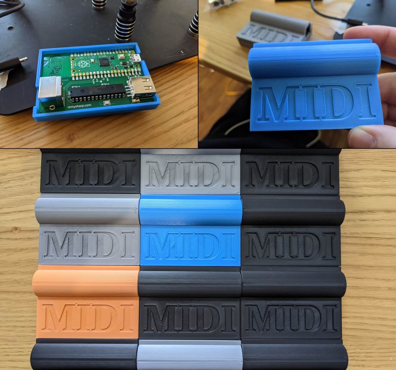
I did just that, and produced 30 custom PCBs with a custom 3D printed housing which have all been sold and sent to people across the globe, including the UK, Germany, Sweden, Netherlands, Brazil and Japan.
How it turned out
There was only four that went out with the "hack" wire going across, the rest were all nice and clean.
On reducing the logic
The first thing I knew, and had prototyped originally was I was using a Raspberry PICO over an Arduino - more on that later.
The original USB Host board that I bought from HobbyTronics also offered the bare IC and included a minimum schematic on how to get the chip to work the way it did on the full board version.
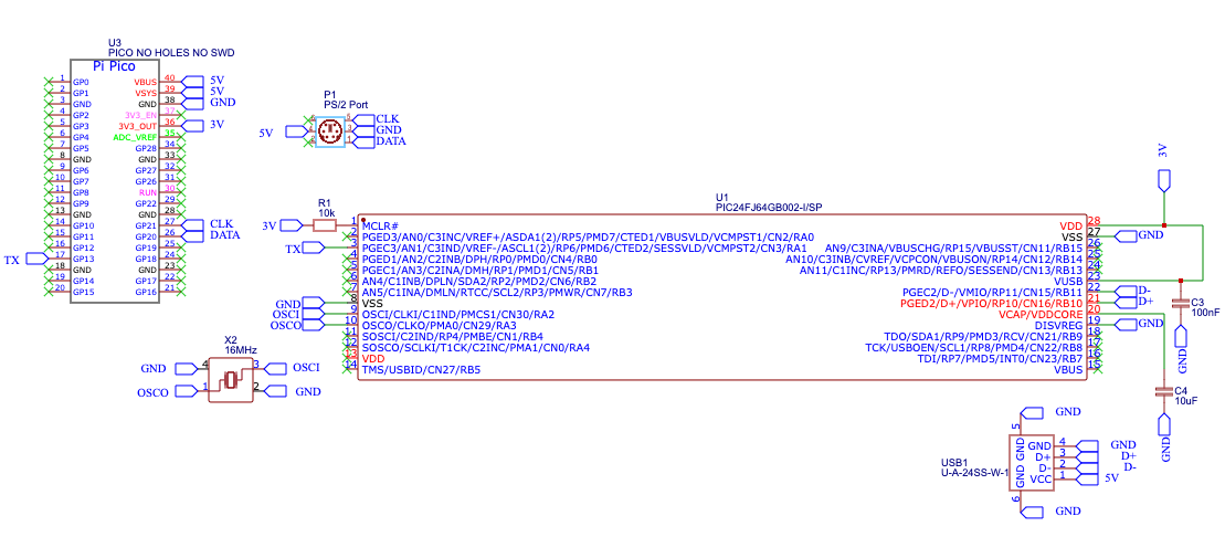
However, if like me you only wanted to read the message from the MIDI controller, then it was possible to reduce this circuit even further than their minimal schematic.
The changes weren't huge, but I could:
- Remove the RX and the diode - since I would only make use of TX
- Remove the voltage regulator and the connected capacitor and resistor because I would be able to take a 3.3V supply from the Raspberry PICO I was going to add
- Remove the resistor on the reset as I wouldn't support it
- Remove the LED and resistor for detection and instead use the built in LED on the PICO
- The 16Mhz crystal and the two connected capacitors could be reduced to a single chip (that basically contain the capacitors inside it)
So now my circuit required the following:
- USB female for the MIDI to connect to
- PS/2 female for the output (PS/2 male houses didn't seem to exist)
- The HobbyTronics USB host chip
- A Raspberry PICO to handle all the MIDI message translation to PS/2 keyboard scan codes
- Two capacitors, one resistor and a 16Mhz oscillator
My own schematic looked like this - the left chip being the Raspberry PICO and the large wide chip being the PIC24FU (the USB host controller):
On using the Raspberry PICO
Although when the PICO came out it didn't really interest me (I'd used Ardunio boards a lot and I didn't see the appeal), I've quickly changed my mind and I really like this board.
The huge pros for me are:
- Readily available in the UK (for fast delivery)
- Cheap - on their own, they cost £3.60, but in batches of five it's £3 and in batches of 10 (which I needed) they're £2.70 (plus £2-3 postage from Pimoroni)
- USB ready
- A boat load of GPIO pins
- Really, really easy to flash, not just for me, but also for the end user - it's a matter of connecting the board with the "boot" button held then the PC will mount the PICO as if it were a drive, and the new firmware can be dropped into the drive
- 3.3V output - for better or worse - but this for me meant I didn't need a voltage regulator (which I'd removed from the schematic)
My original design used an Ardunio, so the code was written for the Arduino. Though I'm comfortable enough with C++ to port the code to upload to the PICO (and I'm probably happier in C than I am in Python), there's a great library called arduino-pico that worked with minimal changes to the code.
I also configured the PICO to behave like a keyboard device over the micro USB port. This meant that if the owner didn't have a Spectrum Next, but instead had a MiSTer or just wanted to connect it to the PC emulator Cspect - the kit could plug directly into the target machine's USB port and work exactly the same way.
Making my own PCB
On recommendations, I used EasyEDA for the PCB design work. I'd watched a few videos on the process and started the workflow with the schematic and joining up all the nets.
Once the schematic was done (the picture from earlier) I then converted the schematic to the PCB design which generally dumps everything on to a space and then I needed to carefully arrange the parts and wires so there was no overlapping (obviously!).
What I started with looked like this:
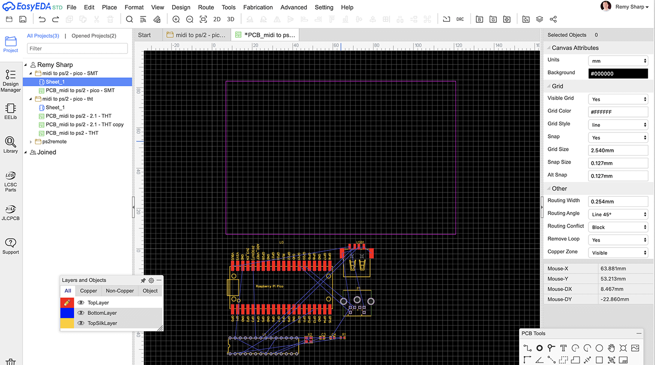
At some point I decided that a rounded corner on the PCB board would be nice, along with a whacking great picture of my face on the board… because I was feeling silly at the time :D
This was the final design:
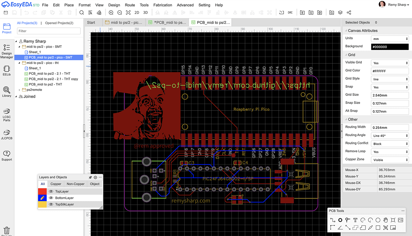
I used JLCPCB for the PCB fabrication though mostly because it was built into EasyEDA.
There were actually two designs that I kept flitting between: one was SMT and the other was THT, the idea being if I had JLC mount the components (not the PICO or main chips, but the smaller components like the oscillator and capacitors) then I'd use SMT, but if I was going to do it all myself THT would just be simpler.
In the end I ordered SMT and I happened to have the exact number of parts to meet their initial 5 soldered components.
The price is, I think, fairly reasonably (or actually pretty cheap) - but where the price really does bump up is the postage. In my case, my first order was 5 PCBs with SMT assembly. The merchandise cost was $11, but the postage was $37.48 - so it does make sense to bulk out the order.
Of course, my first design that I printed wasn't final, and it came with some fun bugs!
PCB bugs
The arrival of the PCB was very cool (for a geek) and I went about soldering the components on to immediately run into problems.
The first was I had assumed that if I ran power into the VBUS on the PICO then that it would power the PICO, but that isn't the case (or… I don't think it was). So I needed to bridge the VBUS to the VSYS which I did with a very short bit of wire - I had tried bridging with solder but either I'm no good at it, or it just wouldn't stick.
The second major problem I ran into was that I had assumed that I could use any pin for TX which the USB host ran in to. This absolutely isn't the case. The PICO does include a lot of pins for UART but it's not every pin.
So you might be able to see from the pictures below, I had to bridge from the UART pins on the left of the PICO all the way across to the right of the PICO - slightly spoiling the whole fanciness of the PCB.
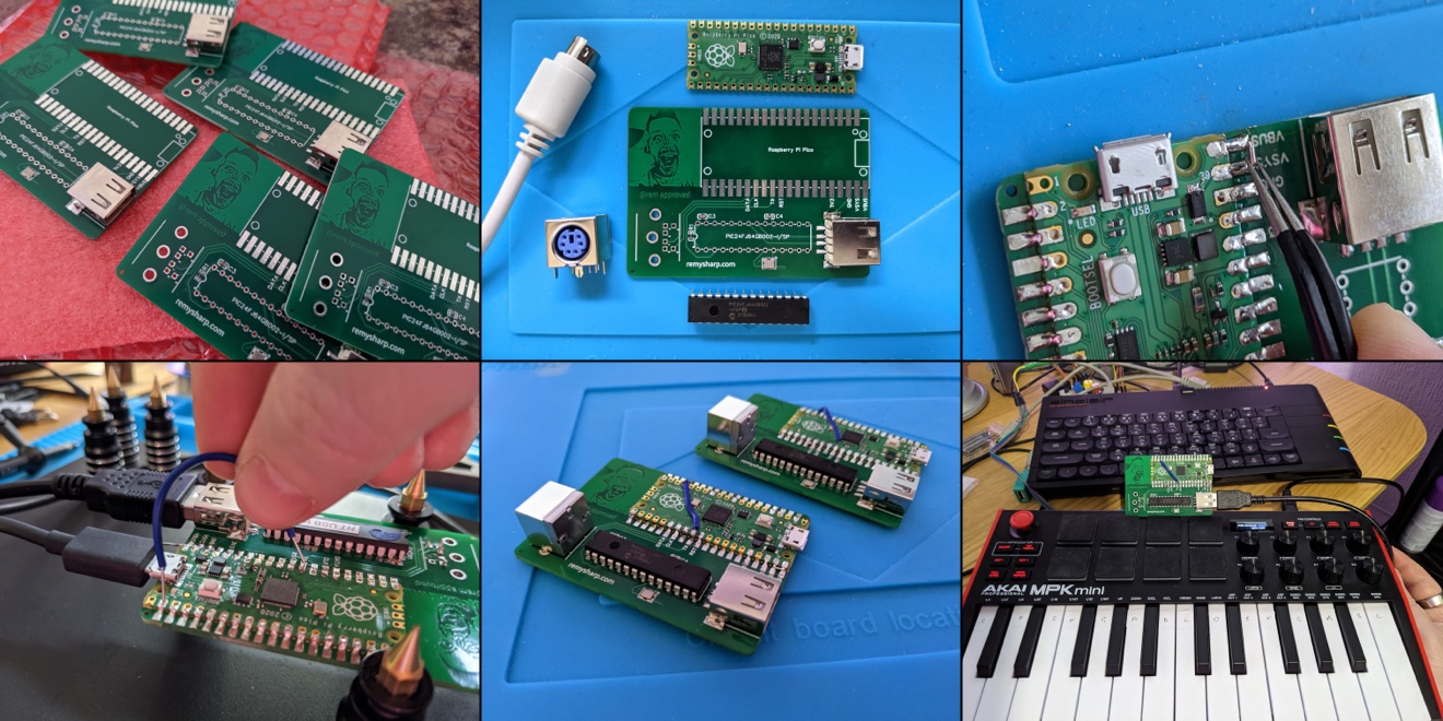
Once those two bridges were in place, and I had updated the PICO software it actually worked. The MIDI controller connected and my kit would translate the messages to keyboard scan codes to the Spectrum Next.
Since this was just a small run of 5 boards, I made the fixes to the schematic and PCB for the main run of 25 boards so I didn't need nasty bridges to make it work.
The icing on the cake: enclosure
Just to add more things to learn, I decided this would be the project that I design a 3D enclosure and print it (on my newly acquired Pursa i3 MK3S+ - thanks Seb for the recommendation).
Having no experience with 3D design, I settled on using Tinkercad probably because it was the most basic - and I used a systematic approach of: add cube, subtract shape, repeat until I had something I liked.
With my calipers handy, I went about printing slices of my design to prototype and check clearance tolerances and used a fairly simple lip method to keep the lid and base connected.
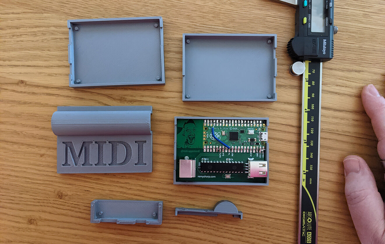
In the end, I had something that held the PCB snug and could be opened with a little bit of force, and looked, I think, fairly smart, and all 30 kits made their way to individuals around the world.
